
Parameter 1 is used for all exits.
This is the address of a 44 byte Communication Area, containing information describing selected system conditions either at the time the exit is invoked or after exit processing.
The following is a breakdown of the fields in the Communication Area.
Bytes 0–3: Address of User Parameter List
This field is only for the BEFORE COMMAND and AFTER COMMAND exits (XLBCEUSR, XLACEUSR).
It is the address of the user parameter list as passed to tableBASE by the application program. The user parameter list includes TBPARM (if supplied), TB-COMMAND-AREA, and any other tableBASE parameters associated with the current command. Usage of the DKL supplied DSECTs for the various parameter areas is recommended.
Byte 4: Environment Indicator
The single byte area contains a code indicating the environment in which tableBASE is running, as listed in Table 19.
|
Environment Indicator |
Environment Description |
|---|---|
|
B |
Batch |
|
C |
CICS |
|
I |
IMS Transaction Manager |
|
D |
DB2 managed stored procedure address space (SPAS) |
|
W |
WLM (WorkLoad manager) managed stored procedure address space (SPAS) |
Byte 5: Exit Indicator
This single byte area contains a code that indicates which of the six exits is in effect, as listed in Table 20.
|
Value |
Exit Level |
Exit Description |
|---|---|---|
|
X’00’ |
XLBCEUSR |
BEFORE COMMAND exit. |
|
X’01’ |
XLACEUSR |
AFTER COMMAND exit. |
|
X’02’ |
XLARIUSR |
AFTER REGION INITIALIZATION exit. |
|
X’03’ |
XLBRTUSR |
BEFORE REGION TERMINATION exit. |
|
X’04’ |
XLATIUSR |
AFTER THREAD INITIALIZATION exit. |
|
X’05’ |
XLBTTUSR |
BEFORE THREAD TERMINATION exit. |
Byte 6: Status Indicator
This byte is used to indicate several types of abends that may have occured in tableBASE. It could also indicate whether the user has selected to issue a user-initiated abend or bypass processing for a tableBASE command. The bit settings and descriptions are listed in Table 21.
|
Value |
Description |
|---|---|
|
X’80’ |
This bit indicates that there has been an abend in the main task in the region or the particular thread that is executing. It is set on by the exit manager at the time of calling the BEFORE THREAD TERMINATION and BEFORE REGION TERMINATION exits (XLBTTUSR, XLBRTUSR). Note:
This bit does not appear to be set on for all types of abends.
|
|
X’40’ |
This bit indicates that there has been an abend in the mother task. It is set on by the exit manager at the time of calling the BEFORE COMMAND, AFTER COMMAND, BEFORE THREAD TERMINATION and BEFORE REGION TERMINATION exits (XLBCEUSR, XLACEUSR, XLBTTUSR, XLBRTUSR). Note:
This bit does not appear to be set in batch even if Multitasking=Y.
|
|
X’20’ |
This bit indicates that there has been an internal tableBASE abend. This bit is set on by the exit manager at the time of calling the BEFORE THREAD TERMINATION and BEFORE REGION TERMINATION exits (XLBRTUSR, XLBTTUSR) if the main task in the region or the particular thread that is executing abends. Note:
This bit does not appear to be set on for all types of abends.
|
|
X’04’ |
If this bit is set on by the BEFORE COMMAND or AFTER COMMAND exits (XLBCEUSR, XLACEUSR), the exit manager will issue an abend after return from the exit, unless the current task is the main task running in a multitasking environment, i.e. if bit X’40’ of the status indicator is on and MULTITASKING=Y is set, the abend will not be issued. When the abend is issued, the following message will appear in the JES log: where nnnn is the user error code in bytes 20-23 of the communication area, xx is the tableBASE command and yyyyyyyy is the table name. |
|
X’02’ |
If this bit is set on by the BEFORE COMMAND exit (XLBCEUSR) program, execution of the current tableBASE command will be bypassed upon return from the exit. If an AFTER COMMAND exit (XLACEUSR) exists, it will be executed. This bit must be reset to prevent subsequent commands from being bypassed. |
Byte 7: Reserved
Bytes 8-15: JOBNAME / USERID
The content of the 8-byte JOBNAME/USERID parameter varies depending on the exit:
- for the AFTER REGION INITIALIZATION (XLARIUSR) and BEFORE REGION TERMINATION (XLBRTUSR) exits, it contains the JOBNAME
- for the BEFORE COMMAND, AFTER COMMAND, AFTER THREAD INITIALIZATION and BEFORE THREAD TERMINATION exits (XLBCEUSR, XLACEUSR, XLATIUSR, XLBTTUSR), it contains the USERID.
Bytes 16-19: Address of Extended Field Definition Area
This is new with Release 6.1.0 and contains the address of the extended field definition area allowing access to the fields specified by the EXITFLD parameter in the DK1EXDFN TYPE=INITIAL macro. For more information on the extended field definition area, see Extended Field Definition Area Layout.
Bytes 20-23: User Exit Assigned Error Code
This field is new with Release 6.1.0. It contains the user assigned error code for abends forced by setting the Status Indicator (byte 6 of the Communication Area) to X’04’ by the BEFORE COMMAND or AFTER COMMAND user exits.
Acceptable values for this field are from 102 to 199. The value set in this field remains until it is reset by another user exit. If the value in this field is zero or outside the range of acceptable values, the default user abend error code of 101 will be used.
This error code is displayed in the DK100400E error message described in Table 21.
Bytes 24-27: Length of Global Work Area
This is the length of the Global Work Area which was defined in the GLBLWORK parameter of the DK1EXDFN TYPE=INITIAL macro. This field is new with Release 6.1.0.
Bytes 28-31: Length of Shared Work Area
This is the length of the Shared Work Area which was defined in the SHRDWORK parameter of the DK1EXDFN TYPE=INITIAL macro. This field is new with Release 6.1.0.
Bytes 32-35: Length of Private Work Area
This is the length of the Private Work Area which was defined in the PRVTWORK parameter of the DK1EXDFN TYPE=ENTRY macro. This field is new with Release 6.1.0.
Bytes 36-43: Reserved
Extended Field Definition Area Layout
This data area is addressed by bytes 16-19 of the Communication Area and its fields are defined in the EXITFLD parameter of the DK1EXDFN TYPE=INITIAL macro. For each field that is specified in the EXITFLD parameter, there will be an associated Extended Field Definition Area and a corresponding Field Value. Figure 25 below shows the layout of the Extended Field Definition Area.
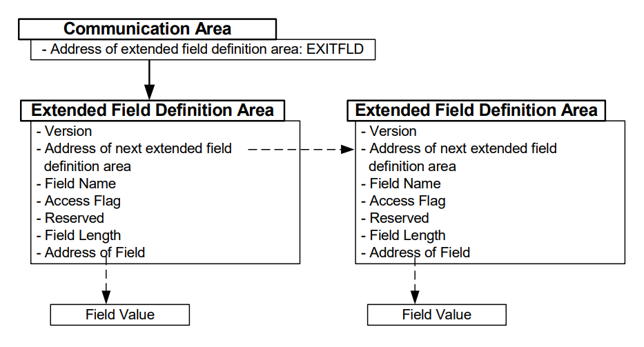
Bytes 0-3: Version
This field contains the version number for the interface to the extended field definition area. The format is xvvv where vvv is the version number. For this first release, it is set to ‘x603’. This field allows the user exits to verify that the format of the extended field definition area is at the correct level for the exit that is using it.
Bytes 4-7: Address of next extended field definition area
This is the address of the next extended field definition area, if there is one. It is zero if there are no more extended field definition areas.
Bytes 8-23: Field Name
This is the field name for the field that is being passed back in the extended field definition area. The value of the field name is the same as that specified in the EXITFLD parameter of the DK1EXDFN macro.
Byte 24: Access Flag
This byte indicates the type of access that is allowed on the field returned. The descriptions are listed in Table 22.
|
Access Flag |
Description |
|---|---|
|
R |
This field is available for read-only access. This setting should be on for all fields that are accessible by the exit. |
|
N |
The field name that was specified is not available for any exit. |
|
U |
The field name that was specified is not available for this type of exit. |
Byte 25: Reserved
Bytes 26-27: Field Length
This is a halfword binary field containing the length of the field being passed.
Bytes 27-30: Address of Field
This is the address of the actual memory area where the value of the field can be found.
Field Value
This is the actual data for the field that was requested in the EXITFLD parameter of the DK1EXDFN TYPE=INITIAL macro. It is the area pointed to by bytes 27-30 (Address of Field) of the Extended Field Definition Area. The maximum length of this area is 80 bytes.